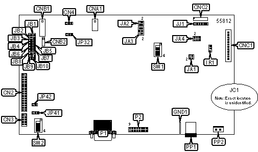
DIGITAL VIEW COMPANY
AC-0800 (4164200-0X)
| Card Type | Video interface controller |
| Video Chip Set | Unidentified |
| Maximum Video Memory | Unidentified |
| Video Types Supported | VGA, SVGA |
| Highest Resolution Supported | 800 x 600 |
| Data Bus | External |

CONNECTIONS |
|||
Function |
Label |
Function |
Label |
| Panel signal connector | CN2 | Unidentified | GND1 |
| Panel signal connector | CN3 | IR connector | IR1 |
| LED connector | CN4 | RS-232 serial interface | JJ1 |
| Auxiliary power connector | CNA1 | VGA analog input port | P1 |
| Backlight inverter connector | CNB1 | VGA input interface | P2 |
| Backlight inverter connector (alternate) | CNB2 | DC power connector | PP1 |
| Function controls connector | CNC1 | DC power connector (alternate) | PP2 |
| Function controls connector (alternate) | CNC2 | ||
USER CONFIGURABLE SETTINGS |
|||
Function |
Label |
Position |
|
| » | Factory configured - do not alter | JA1 | Pins 1 & 3, 2 & 4 closed |
| » | Factory configured - do not alter | JA2 | Pins 1 & 3, 2 & 4 closed |
| Panel voltage supply is +3.3V | JA3 | Pins 1 & 3, 2 & 4 closed | |
| Panel voltage supply is +5V | JA3 | Pins 3 & 5, 4 & 6 closed | |
| RS-232 voltage is +12V | JA4 | Pins 1 & 3, 2 & 4 closed | |
| RS-232 voltage is +5V | JA4 | Pins 3 & 5, 4 & 6 closed | |
| » | Backlight brightness PWM signal level is +5V | JB1 | Pins 1 & 2 closed |
| Backlight brightness PWM signal level is +12V | JB1 | Pins 2 & 3 closed | |
| Backlight inverter on/off control signal high = CCFT ON | JB3 | Pins 1 & 2 closed | |
| Backlight inverter on/off control signal low = CCFT ON | JB3 | Pins 2 & 3 closed | |
| » | Factory configured - do not alter | JB4 | Pins 1 & 2 closed |
| » | Backlight brightness signal = voltage | JB5 | Pins 1 & 2 closed |
| Backlight brightness signal = PWM | JB5 | Pins 2 & 3 closed | |
| » | Backlight brightness control = VR | JB6 | Pins 1 & 2 closed |
| Backlight brightness control = voltage or PWM | JB6 | Pins 2 & 3 closed | |
| » | Factory configured - do not alter | JB7 | Open |
| » | Factory configured - do not alter | JB8 | Pins 2 & 3 closed |
| » | Backlight inverter status is active low | JB9 | Pins 1 & 2 closed |
| Backlight inverter status is active high | JB9 | Pins 2 & 3 closed | |
| » | Backlight power control by MCU | JB10 | Pins 1 & 2 closed |
| Backlight power control always enabled | JB10 | Pins 2 & 3 closed | |
| » | Factory configured - do not alter | JC1 | Open |
| Panel type is LG LP064V1 | JP41 | Pins 1 & 2 closed | |
| Panel type is not LG LP064V1 | JP41 | Open | |
| » | Factory configured - do not alter | JP42 | Open |
| » | Factory configured - do not alter | SW1/1 | On |
| » | Factory configured - do not alter | SW1/2 | On |
| Clock phase change (TFT panel) | SW2/1 | Unidentified | |
| Video input and output locked | SW2/2 | On | |
| Video input and output not locked | SW2/2 | Off | |
| » | Factory configured - do not alter | SW2/3 | Off |
| » | Factory configured - do not alter | SW2/4 | Off |
| Note: Settings for JB2 is dependant of the inverter used. | |||
BACKLIGHT INVERTER VOLTAGE SELECTION |
|
Backlight inverter on/off control signal |
JB2 |
| High = +12V | Pins 1 & 2 closed |
| High = +5V | Pins 2 & 3 closed |
| High = Open collector | Open |
| Note: Settings for JB2 is dependant of the inverter used. | |
PANEL VIDEO SELECTION |
|||
Video Type |
JP32 | SW1/3 | SW1/4 |
| SVGA | Pins 1 & 2 closed | Off | On |
| VGA | Open | Off | Off |
MISCELLANEOUS TECHNICAL NOTES |
This video controller is for use with LCD and TFT flat panel display applications.Adequate insulation should be used for all areas of the PCB, especially in high voltage parts such as the inverter. Settings can be controlled by an analog VR or digital function control device. |