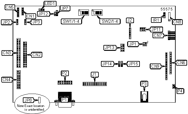
DIGITAL VIEW COMPANY
AC-1024 V.3 (4163400-3X)
| Card Type | Video card |
| Video Chip Set | Unidentified |
| Maximum Video Memory | Unidentified |
| Video Types Supported | VGA, SVGA, XGA |
| Highest Resolution Supported | 1024 x 768 |
| Data Bus | None |

CONNECTIONS |
|||
Function |
Label |
Function |
Label |
| Auxiliary power connector | CN1 | IR connector | IR1 |
| LCD panel connector A | CN2 | Video add-on connector | J1 |
| LCD panel connector B | CN3 | RS-232 linkage | J2 |
| 8-bit LCD panel connector | CN4 | LED connector | LED1 |
| Backlight inverter connector | CN5 | VGA analog in | P1 |
| Function control connector | CN6 | Alternative VGA in | P2 |
| Audio board connector | CN7 | DC power connector | P3 |
| Reserved | CN8 | Alternative DC power connector | P4 |
| Alternative Function control connector | CN9 | ||
USER CONFIGURABLE SETTINGS |
|||
Function |
Label |
Position |
|
| » | Factory configured - do not alter | JP1 | Pins 1 & 2 closed |
| » | Factory configured - do not alter | JP1 | Pins 3 & 4 closed |
| Backlight inverter polarity control - signal "high" = CCFT on | JP3 | Pins 1 & 2 closed | |
| Backlight inverter polarity control - signal "low" = CCFT on | JP3 | Pins 2 & 3 closed | |
| +3.3V panel power voltage selected | JP7 | Pins 1 & 2 closed | |
| +5V panel power voltage selected | JP7 | Pins 2 & 3 closed | |
| » | Factory configured - do not alter | JP8 | Unidentified |
| +12V RS-232 signal level selected | JP11 | Pins 1 & 3, 2 & 4 closed | |
| +5V RS-232 signal level selected | JP11 | Pins 3 & 5, 4 & 6 closed | |
| +12V safe panel power enabled | JP12 | Pins 1 & 2 closed | |
| +12V safe panel power disabled | JP12 | Open | |
| Vertical filter enabled | SW1/1 | On | |
| Vertical filter disabled | SW1/1 | Off | |
| Display enabled during Sync | SW2/2 | On | |
| Display disabled during Sync | SW2/2 | Off | |
| Volume enabled | SW2/4 | On | |
| Volume disabled | SW2/4 | Off | |
P ANEL SELECTION |
|||
S etting |
S W1/2 |
S W1/3 |
S W1/4 |
X GA (dual pixels) |
O n |
O ff |
O n |
| XGA (single pixels) | On | Off | Off |
| SVGA | Off | On | On |
| VGA | Off | Off | On |
P ANEL CLOCK SELECTION |
|||
S etting |
J P13 |
J P14 |
J P15 |
X GA panel |
P ins 3 & 4 closed |
P ins 1 & 2 closed |
P ins 1 & 2 closed |
| SVGA panel | Pins 3 & 4 closed | Pins 1 & 2 closed | Pins 2 & 3 closed |
| VGA panel | Pins 3 & 4 closed | Pins 1 & 2 closed | Open |
B ACKLIGHT INVERTER SIGNAL LEVEL SELECTION |
|
S etting |
J P2 |
| On/off control signal "High" = +12V | P ins 1 & 2 closed |
| On/off control signal "High" = +5V | Pins 2 & 3 closed |
| On/off control signal "High" = open collector | Open |
MISCELLANEOUS TECHNICAL NOTES |
C lock phase selection is controlled by SW2/1. Switch SW2/1 on and off to adjust image stability.Vertical stability is controlled by SW2/3. Switch SW2/3 on and off to adjust image vertical stability. |