CONTROLWARE COMMUNICATIONS SYSTEMS, INC.
PRIMUS
| Card Type | ISDN/2MS/2MU TA, Ethernet router |
| Chipset | Unidentified |
| Network Transfer Rate | 10Mbps |
| Topology | Star |
| Wire Type | Unshielded twisted pair |
| TA Transfer Rate | 1.92Mbps/1.984Mbps/2.048Mbps |
| TA Protocol | Unidentified |
| TA Frame Type | HDB3 |
| Data Bus | Serial |

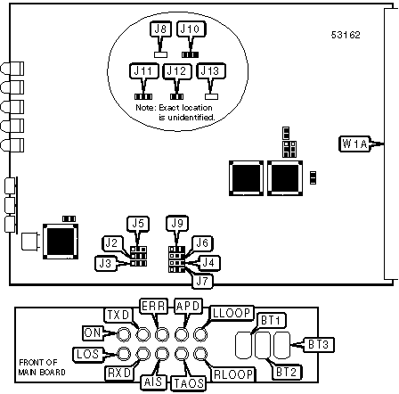
CONNECTIONS |
|||
Function |
Label |
Function |
Label |
| Remote loopback test button | BT1 |
Transmit All Ones simulation button | BT3 |
| Local loopback test button | BT2 |
Header to interface board W1B | W1A |
USER CONFIGURABLE SETTINGS |
|||
Setting |
Label |
Position |
|
| » | CRC4 check enabled | J2 |
Pins 2 & 3 closed |
| CRC4 check disabled | J2 |
Pins 1 & 2 closed |
|
| » | Internal clock source selected | J3 |
Pins 1 & 2 closed |
| External clock source selected | J3 |
Pins 2 & 3 closed |
|
| » | External clock not through entire transmission system | J4 |
Pins 1 & 2 closed |
| External clock through entire transmission system | J4 |
Pins 2 & 3 closed |
|
| » | X.21 serial port is DCE and is clock master | J5 |
Pins 1 & 2 closed |
| X.21 serial port is DTE and is clock slave | J5 |
Pins 2 & 3 closed |
|
| » | Factory configured - do not alter | J8 |
Open |
USER CONFIGURABLE SETTINGS (CON’T) |
|||
Setting |
Label |
Position |
|
| » | Adapter is G.703 slave | J9 |
Pins 2 & 3 closed |
| Adapter is G.703 master | J9 |
Pins 1 & 2 closed |
|
| » | Factory configured - do not alter | J10 |
Pins 1 & 2 closed |
| » | Factory configured - do not alter | J11 |
Pins 2 & 3 closed |
| » | Factory configured - do not alter | J12 |
Closed |
| » | Factory configured - do not alter | J13 |
Open |
LINE SPEED SELECTION |
|||
Setting |
J6 |
J7 |
|
| » | 1.92Mbps |
Pins 1 & 2 closed |
Pins 1 & 2 closed |
1.984Mbps |
Pins 2 & 3 closed |
Pins 1 & 2 closed |
|
2.048Mbps |
N/A |
Pins 2 & 3 closed |
|
DIAGNOSTIC LED(S) |
|||
LED |
Color |
Status |
Condition |
ON |
Green |
On |
Power is on |
ON |
Green |
Off |
Power is off |
LOS |
Red |
On |
Loss Of Signal condition occurred |
LOS |
Red |
Off |
Loss Of Signal condition did not occur |
TXD |
Green |
On |
Adapter is transmitting data |
TXD |
Green |
Off |
Adapter is not transmitting data |
RXD |
Green |
On |
Adapter is receiving data |
RXD |
Green |
Off |
Adapter is not receiving data |
ERR |
Yellow |
On |
CRC4 error detected |
ERR |
Yellow |
Off |
CRC4 error not detected |
AIS |
Yellow |
On |
Alarm Indication Signal condition occurred |
AIS |
Yellow |
Off |
Alarm Indication Signal condition did not occur |
APD |
Yellow |
On |
Automatic propogation time compensation was successful |
APD |
Yellow |
Off |
Automatic propogation time compensation was not successful |
TAOS |
Yellow |
On |
Adapter is performing Transmit All Ones simulation |
TAOS |
Yellow |
Off |
Adapter is not performing Transmit All Ones simulation |
LLOOP |
Yellow |
On |
Adapter is performing local loopback test |
LLOOP |
Yellow |
Off |
Adapter is not performing local loopback test |
RLOOP |
Yellow |
On |
Adapter is performing remote loopback test |
RLOOP |
Yellow |
Off |
Adapter is not performing remote loopback test |

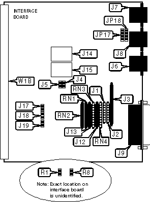
CONNECTIONS |
|||
Function |
Label |
Function |
Label |
| Unshielded twisted pair connector | J6 |
Unidentified | J14 |
| V.24 serial port for supervisor terminal | J7 |
Unidentified | J15 |
| ISDN PRI interface | J8 |
Header to main board W1A | W1B |
| X.21 serial port | J9 |
||
| Note:Not all PRIMUS boards support J6 and J7. Those that do not will not provide Ethernet support. | |||
USER CONFIGURABLE SETTINGS |
|||
Setting |
Label |
Position |
|
| » | Factory configured - do not alter | J3 |
Unidentified |
| » | Signal ground connected not to chassis ground | J10 |
Open |
| Signal ground connected to chassis ground | J10 |
Closed |
|
| » | Factory configured - do not alter | J12 |
Unidentified |
| » | Factory configured - do not alter | J13 |
Unidentified |
| » | Factory configured - do not alter | RN1 |
Unidentified |
| » | Factory configured - do not alter | RN2 |
Unidentified |
X.21 B SIGNAL CONFIGURATION |
|||
Setting |
J5 |
J19 |
|
| » | Data may not be sent via B signal |
Closed |
Open |
Data may be sent via B signal |
Open |
Closed |
|
ARCNET SOCKET CONFIGURATION |
|||
Setting |
J17 |
J18 |
|
| » | Not connected to W1B |
Open |
Open |
Connected to W1B |
Closed |
Closed |
|
CLOCK SOURCE SELECTION |
||||
Setting |
J1 |
J2 |
J4 |
|
| » | Slave |
Installed |
Not installed |
Open |
Internal |
Not installed |
Installed |
Open |
|
External |
Not installed |
Installed |
Closed |
|
ISDN INTERFACE CONFIGURATION |
|||||||
Transmit Pair |
Receive Pair |
Chassis Ground |
Signal Ground |
JP17 |
JP18 |
R1 |
R8 |
Pins 4 & 5 |
Pins 3 & 6 |
None |
None |
Pins 2 & 3 |
Pins 2 & 3 |
Open |
Open |
Pins 4 & 5 |
Pins 1 & 2 |
None |
None |
Pins 1 & 2 |
Pins 1 & 2 |
Open |
Open |
Pins 4 & 5 |
Pins 1 & 2 |
None |
None |
Pins 1 & 2 |
Pins 1 & 2, 3 & 4 |
Open |
Open |
Pins 4 & 5 |
Pins 1 & 2 |
Pins 3 & 6 |
None |
Pins 1 & 2 |
Pins 1 & 2, 3 & 4 |
Closed |
Open |
Pins 4 & 5 |
Pins 1 & 2 |
None |
Pins 3 & 6 |
Pins 1 & 2 |
Pins 1 & 2, 3 & 4 |
Open |
Closed |
| Note:Pins designated for J17 and J18 are in the closed position. | |||||||
RECEIVER OPEN CIRCUIT FAILSAFE |
|||
Setting |
RN3 |
RN4 |
|
| » | Disabled |
Not installed |
Not installed |
Ground |
Installed |
Not installed |
|
Power supply |
Not installed |
Installed |
|