D-LINK
DFE-854
|
Card Type |
Ethernet Transceiver |
|
NIC Type |
Ethernet |
|
Boot ROM |
Not available |
|
Network Transfer Rate |
100Mbps |
|
Topology |
Star, Peer-Peer |
|
Wiring Type |
Fiber optic |
|
Data Bus |
External |

|
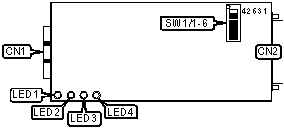
CONNECTIONS |
|||
|
Function |
Label |
Function |
Label |
|
Fiber SC connector |
CN1 |
MII connector |
CN2 |
|
USER CONFIGURABLE SETTINGS |
||
|
Function |
Label |
Position |
|
Enable full-duplex/auto negotiate mode |
SW1/6 |
Off |
|
Enable half-duplex mode |
SW1/6 |
On |
|
PHY ADDRESS SELECTION |
|||||
|
Setting |
SW1/1 |
SW1/2 |
SW1/3 |
SW1/4 |
SW1/5 |
|
00h |
Off |
Off |
Off |
Off |
Off |
|
01h |
Off |
Off |
Off |
Off |
On |
|
02h |
Off |
Off |
Off |
On |
Off |
|
03h |
Off |
Off |
Off |
On |
On |
|
10h |
On |
Off |
Off |
Off |
Off |
|
1Ch |
On |
On |
On |
Off |
Off |
|
1Dh |
On |
On |
On |
Off |
On |
|
1Eh |
On |
On |
On |
On |
Off |
|
1Fh |
On |
On |
On |
On |
On |
|
Note: A total of 30 address settings are available. The switches are a binary representation of the hexadecimal memory addresses. SW1/1 is the Most Significant Bit and SW1/5 is the Least Significant Bit. The switches have the following hexadecimal values: SW1/5=01h, SW1/4=02h, SW1/3=04h, SW1/2=08h, SW1/1=10h. Turn on the switches and add the values of the switches to obtain the correct memory address. (Off=0, On=1) |
|||||
|
DIAGNOSTIC LED(S) |
|||
|
LED |
Color |
Status |
Condition |
|
LED1 |
Green |
On |
Power is on |
|
LED1 |
Green |
Blinking |
Data is being transmitted |
|
LED1 |
Green |
Off |
Power is off |
|
LED2 |
Green |
On |
Network connection is good |
|
LED2 |
Green |
Blinking |
Data is being received |
|
LED2 |
Green |
Off |
Network connection is broken |
|
LED3 |
Green |
On |
Operating at full-duplex |
|
LED3 |
Green |
Off |
Operation at half-duplex |
|
LED4 |
Yellow |
On |
Data collision has occurred |
|
LED4 |
Yellow |
Off |
No collision is detected |