IMC NETWORKS CORPORATION
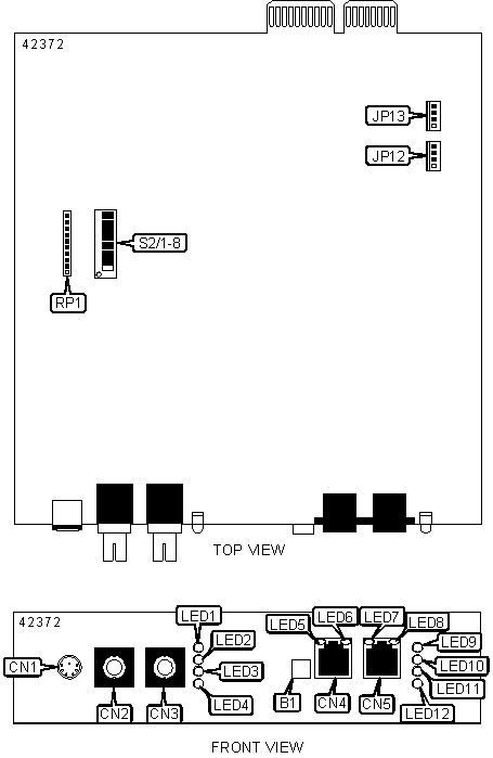
FIBERLINX (SC VERSION)
| Card Type | Network Interface Card |
| NIC Type | Ethernet |
| Boot ROM | Not Available |
| Network Transfer Rate | 10 Mbps |
| Topology | Star |
| Wiring Type | Fiber, UTP |
| Data Bus | Proprietary |

CONNECTIONS |
|||
Function |
Label |
Function |
Label |
| Serial/switch connector | CN1 |
RJ-45 UTP management port connector | CN5 |
| Fiber optic SC data port connector (transmit) | CN2 |
Unidentified | JP12 |
| Fiber optic SC data port connector (receive) | CN3 |
Unidentified | JP13 |
| RJ-45 UTP data port connector | CN4 |
Unidentified | RP1 |
USER CONFIGURABLE SETTINGS |
|||
Function |
Label |
Position |
|
| Pass-through connection selected on UTP data port | B1 | In | |
| Crossover connection selected on UTP data port | B1 | Out | |
| » | Factory configured - do not alter | S2/1 | On |
| » | Factory configured - do not alter | S2/2 | On |
| » | Fiber data port select Half-Duplex mode | S2/3 | Off |
| Fiber data port select Full-Duplex mode | S2/3 | On | |
| » | UTP data port select Half-Duplex mode | S2/4 | Off |
| UTP data port select Full-Duplex mode | S2/4 | On | |
SNMP MANAGEMENT TRAFFIC SELECTION |
|||
Setting |
S2/5 | S2/6 | |
| » | SNMP commands accepted from UTP data port | On | Off |
SNMP commands accepted from fiber data port |
On | On | |
| SNMP commands accepted from UTP management port | Off | On | |
SNMP commands not accepted |
Off | Off | |
UNIT CONFIGURATION |
|||
Setting |
S2/7 | S2/8 | |
| » | Standalone unit |
Off | Off |
Remote unit (slave) |
On | Off | |
Host unit (master) |
Off | On | |
DIAGNOSTIC LED(S) |
|||
LED |
Color |
Status |
Condition |
LED1 |
Yellow |
On |
Full-Duplex mode is selected on fiber data port |
LED1 |
Yellow |
Off |
Full-Duplex mode is not selected on fiber data port |
LED2 |
Green |
Blinking |
Data is detected on fiber data port |
LED2 |
Green |
Off |
Data is not detected on fiber data port |
| LED3 | Green | On | Fiber link is good |
| LED3 | Green | Off | Fiber link is broken |
| LED4 | Green | On | Fault detected on fiber data port, trouble shooting feature enabled |
| LED4 | Green | Off | Fault not detected on fiber data port, trouble shooting feature disabled |
| LED5 | Green | On | UTP link is good |
| LED5 | Green | Off | UTP link is broken |
LED6 |
Yellow |
On |
Full-Duplex mode is selected on UTP data port |
LED6 |
Yellow |
Off |
Full-Duplex mode is not selected on UTP data port |
| LED7 | Green | On | UTP link is good (management port) |
| LED7 | Green | Off | UTP link is broken (management port) |
| LED8 | Yellow |
On |
Full-Duplex mode is selected on UTP management port |
| LED8 | Yellow |
Off |
Full-Duplex mode is not selected on UTP management port |
| LED9 | Yellow | On | Far end is detected |
| LED9 | Yellow | Off | Far end is not detected |
| LED10 | Green | On | UTP link is good (remote data port) |
| LED10 | Green | Off | UTP link is broken (remote data port) |
| LED11 | Green | Blinking | SNMP activity detected |
| LED11 | Green | Off | SNMP activity not detected |
| LED12 | Green | Blinking | UTP activity detected |
| LED12 | Green | Off | UTP activity not detected |
Note: LED9 and LED10 will not function with single unit configuration. |
|||
MISCELLANEOUS TECHNICAL NOTES |
U nit installs into any slot of manufactures already installed PowerChassis. |