AMPRO COMPUTERS, INC.
LITTLE BOARD/P5X
| Device Type | Mainboard |
| Processor | Pentium |
| Processor Speed | 133/166/200/233/266MHz |
| Chip Set | Unidentified |
| Maximum Onboard Memory | 256MB (EDO & SDRAM supported) |
| Cache | 512KB |
| BIOS | Unidentified |
| Dimensions | 146mm x 203mm |
| I/O Options (backplane) | 32-bit PCI slot (1), Ethernet 100BaseT connector, floppy drive interface, IDE interfaces (2), Ultra SCSI interface, VGA interface, parallel port, PS/2 mouse port, serial ports (4), IR connector, USB connectors (2), PC/104 connectors (2) |

CONNECTIONS |
|||
Purpose |
Location |
Purpose |
Location |
| Flat panel video connector | J3 | CPU power supply | J19 |
| Vee bias supply connector | J4 | Serial interface 1 (RS-485) | J20 |
| Analog video connector | J5 | Ethernet connection | J22 |
| ZV port interface (Video Zoom) | J6 | Compact Flash BIOS | J23 |
| Ethernet RJ-45 connector | J7 | Laptop lid switch simulator | J24/pins 1,2,3 |
| Ethernet connector | J8 | IR connector | J24/pins 4,5,6,7,8 |
| Ultra SCSI interface | J9 | PS/2 Mouse port | J24/pins 9,10,11,12 |
| Power connector | J10 | USB connector 1 | J24/pins 15,17,19,21,23 |
| Serial port 1 & 2 | J11 | USB connector 2 | J24/pins 16,18,20,22,24 |
| IDE interface 1 | J12 | Flat Panel Video connector | J25 |
| Serial port 3 & 4 | J13 | CPU fan power | J28 |
| Floppy drive interface | J14 | Serial port 3 (RS-485) | J29 |
| Parallel port | J15 | External power management option | J30 |
| Utility connector 1 | J16 | PC/104 connector | P1 |
| IDE interface 2 | J17 | PC/104 connector | P2 |
| CPU power supply | J18 | 32-bit PCI slot | PC1 |
USER CONFIGURABLE SETTINGS |
|||
Function |
Label |
Position |
|
| » | Serial 1 RS-485 termination disabled | W1 | Open |
| Serial 1 RS-485 termination enabled | W1 | Closed | |
| » | SCSI TERMPWR disabled | W2 | Open |
| SCSI TERMPWR enabled | W2 | Closed | |
» |
Factory configured - do not alter | W3 |
Unidentified |
» |
Factory configured - do not alter | W4 |
Unidentified |
» |
Factory configured - do not alter | W5 |
Unidentified |
» |
Factory configured - do not alter | W6 |
Unidentified |
» |
Serial 3 RS-485 termination disabled | W7 |
Open |
| Serial 3 RS-485 termination enabled | W7 | Closed | |
| » | Watchdog Timer reset disabled | W8 | Open |
| Watchdog Timer reset enabled | W8 |
Closed |
|
» |
Factory configured - do not alter | W9 |
Open |
| » | External BIOS board connection enabled | W10 | Closed |
| External BIOS board connection disabled | W10 | Open |
|
| » | Flash BIOS programming power enabled | W11 | Closed |
| Flash BIOS programming power disabled | W11 | Open |
|
| » | Compact Flash IDE master | W12 |
Closed |
| Compact Flash IDE slave | W12 | Open |
|
DIMM CONFIGURATION |
|
Size |
Bank 0 |
16MB |
(1) 2M x 64 |
32MB |
(1) 4M x 64 |
64MB |
(1) 8M x 64 |
128MB |
(1) 16M x 64 |
256MB |
(1) 32M x 64 |
ETHRNET INDICATOR LEDS |
|||
LED |
Color |
Ethernet status | Condition |
D1 |
Yellow |
On | Data is being received. |
D1 |
Yellow |
Off | Data is not being received. |
D2 |
Red |
On | Data is being transmitted. |
D2 |
Red |
Off | Data is not being transmitted. |
D3 |
Green |
On | UTP link is good. |
D3 |
Green |
Off | UTP link is broken. |

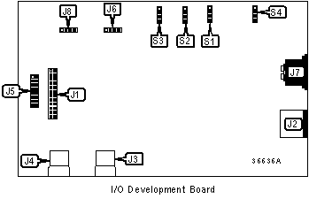
CONNECTIONS |
|||
Purpose |
Location |
Purpose |
Location |
| Utility connector 1 to P5x via J16 | J1 | Utility connector 2 to P5x via J24 | J5 |
| PS/2 Mouse port | J2 | Power connection | J6 |
| USB port 1 | J3 | Keyboard port | J7 |
| USB port 2 | J4 | Reserved | J8 |
USER CONFIGURABLE SETTINGS |
|||
Function |
Label |
Position |
|
| Simulates laptop lid closure | S1 | Unidentified | |
| Power On/Off button switch | S2 | Unidentified | |
| Simulate low-battery condition | S3 | Unidentified | |
| Reset signal to Little Board | S4 | Unidentified | |