CHAINTECH COMPUTER COMPANY, LTD.
CT-6BPV
| Device Type | Mainboard |
| Processor | Pentium II/Celeron |
| Processor Speed | 233/266/300/333/350/366/400/433/450MHz |
| Chip Set | Intel 440BX/440ZX |
| Video Chip Set | ATI |
| Audio Chip Set | ESS |
| Maximum Onboard Memory | 256MB (SDRAM supported) |
| Maximum Video Memory | 8MB |
| Maximum Audio Memory | Unidentified |
| Cache | 0/128/256/512KB (located on the CPU) |
| BIOS | Award |
| Dimensions | 205mm x 255mm |
| I/O Options (mainboard) | Game/MIDI interface, parallel port, PS/2 mouse port, serial port, VGA port, riser slot, USB ports (2), line in, line out, Ethernet 10BaseT connector, Wake-on-LAN connector, SB-Link connector, S-video port, Composite video port, serial interface |
| I/O Options (riser card) | 32-bit PCI slots (2), CD-ROM interface, , floppy drive interface, green PC connector, IDE interface, IR connector, USB ports (2), ATX power connector, speaker/microphone in, Wake-on-LAN connector, SB-Link, S-video port, Composite video port, Modem telephony connector |

CONNECTIONS |
|||
| Purpose | Location |
Purpose | Location |
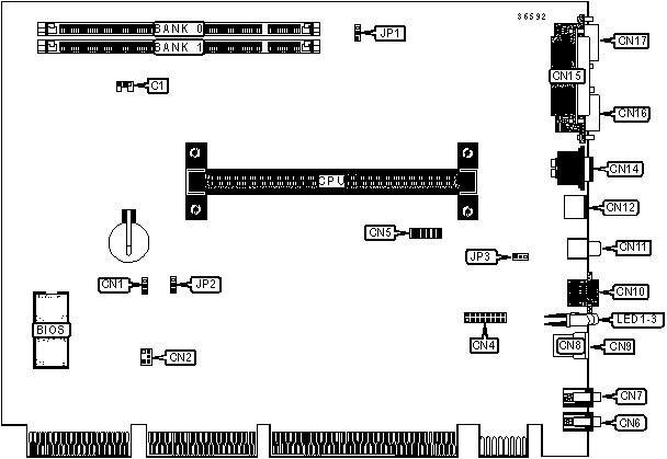
| CPU fan power | C1 | USB port 2 | CN9 |
| Wake-on-LAN connector | CN1 | Ethernet 10BaseT via RJ-45 connector | CN10 |
| SB-Link connector | CN2 | Composite video out | CN11 |
| Game/MIDI interface | CN4 | S-Video out | CN12 |
| Serial interface 2 | CN5 | PS/2 mouse port | CN14 |
| Line out | CN6 | Parallel port | CN15 |
| Line in | CN7 | Serial port 1 | CN16 |
| USB port 1 | CN8 | VGA port | CN17 |
USER CONFIGURABLE SETTINGS |
|||
Function |
Label |
Position |
|
|
On-board VGA enabled | JP1 | Pins 1 & 2 Closed |
| On-board VGA disabled | JP1 | Pins 2 & 3 Closed | |
| » | CMOS memory normal operation | JP2 | Pins 1 & 2 Closed |
|
CMOS memory clear | JP2 | Pins 2 & 3 Closed |
| Keyboard power-on disabled | JP3 | Pins 1 & 2 Closed | |
| Keyboard power-on enabled | JP3 | Pins 2 & 3 Closed | |
DIMM CONFIGURATION |
||
Size |
Bank 0 |
Bank 1 |
16MB |
(1) 2M x 64 |
None |
32MB |
(1) 4M x 64 |
None |
32MB |
(1) 2M x 64 |
(1) 2M x 64 |
48MB |
(1) 4M x 64 |
(1) 2M x 64 |
64MB |
(1) 8M x 64 |
None |
64MB |
(1) 4M x 64 |
(1) 4M x 64 |
80MB |
(1) 8M x 64 |
(1) 2M x 64 |
96MB |
(1) 8M x 64 |
(1) 4M x 64 |
128MB |
(1) 16M x 64 |
None |
128MB |
(1) 8M x 64 |
(1) 8M x 64 |
144MB |
(1) 16M x 64 |
(1) 2M x 64 |
160MB |
(1) 16M x 64 |
(1) 4M x 64 |
192MB |
(1) 16M x 64 |
(1) 8M x 64 |
256MB |
(1) 16M x 64 |
(1) 16M x 64 |
| Note: Board supports SDRAM memory. | ||
CACHE CONFIGURATION |
| Note: 256KB/512KB cache is located on the Pentium II CPU. 128KB cache is located on the Celeron 300A & 333 CPUs. |
DIAGNOSTIC LED(S) |
| Note: Diagnostic information for LEDs 1-3 is not available. |

CONNECTIONS |
|||
| Purpose | Location |
Purpose | Location |
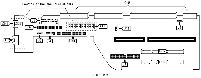
| ATX power connector | ATX |
Turbo LED | J8/Pins 1 & 2 |
| IDE interface | CN1 | Green PC connector | J8/Pins 4 & 5 |
| Floppy drive interface | CN2 | Green PC LED | J8/Pins 6 & 7 |
| USB port 1 | CN3 | Reset switch | J8/Pins 9 & 10 |
| USB port 2 | CN4 | IDE interface LED | J8/Pins 11 & 12 |
| Riser card connectors | CN5 | Over-ride power connector | J8/Pins 13 & 14 |
| IR connector | IR | Speaker 2 | J8/Pins 15-18 |
| CD-ROM interface | J1 | Power LED & keylock | J8/Pins 20-24 |
| Speaker 1 | J3 | Chassis fan power | J11 |
| Speaker & Mic-in connector | J4 | 32-bit PCI slots | PC1 - PC2 |
| Modem telephony connector | J5 | ||
MISCELLANEOUS NOTES |
| Only two USB ports may be in use at the same time. Either both ports on the Mainboard, both ports on the Riser card, or one port on each may be used simultaneously. |