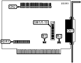
TECMAR
WANGTEK 30631
| Card Type | Digital I/O card |
| I/O Options | Tape drive interface (2) |
| Data Bus | 8-bit ISA |

CONNECTIONS |
|||
Function |
Label |
Function |
Label |
| Tape drive interface | CN1 | Tape drive interface | CN2 |
USER CONFIGURABLE SETTINGS |
|||
Function |
Label |
Position |
|
| » | Disable DMA operation mode | W1 | Closed |
| Enable DMA operation mode | W1 | Open | |
| » | Mainboard is connected to chassis ground | W2 | Closed |
| Mainboard is not connected to chassis ground | W2 | Open | |
DACK SELECTION |
|
Setting |
HDR1 |
DACK1 |
Pins 19 & 20 closed |
DACK2 |
Pins 21 & 22 closed |
| DACK3 | Pins 23 & 24 closed |
SERIAL PORT 1 INTERRUPT SELECTION |
|
IRQ Setting |
HDR1 |
IRQ2 |
Pins 1 & 2 closed |
IRQ3 |
Pins 3 & 4 closed |
| IRQ4 | Pins 5 & 6 closed |
| IRQ5 | Pins 7 & 8 closed |
| IRQ6 | Pins 9 & 10 closed |
| IRQ7 | Pins 11 & 12 closed |
DRQ SELECTION |
|
Setting |
HDR1 |
DRQ1 |
Pins 13 & 14 closed |
DRQ2 |
Pins 15 & 16 closed |
| DRQ3 | Pins 17 & 18 closed |
BASE I/O ADDRESS SELECTION |
||||||||||
Setting |
SW1/1 |
SW1/2 |
SW1/3 |
SW1/4 |
SW1/5 |
SW1/6 |
SW1/7 |
SW1/8 | SW1/9 |
SW1/10 |
| 280h | On | On | On | On | On | On | Off | On | Off | On |
| 288h | On | On | Off | On | On | On | Off | On | Off | On |
| 300h | On | On | On | On | On | On | On | Off | Off | On |
338h |
On | On | Off | Off | Off | On | On | Off | Off | On |
| Note: A total of 255 base address settings are available. The switches are a binary representation of the decimal memory addresses. SW1/8 is the Most Significant Bit and switch SW1/1 is the Least Significant Bit. The switches have the following decimal values: SW1/8=32768, SW1/7=16384, SW1/6=8192, SW1/5=4096, SW1/4=2048, SW1/3=1024, SW1/2=512, SW1/1=256. Turn off the switches and add the values of the switches to obtain the correct memory address. (Off=1, On=0) | ||||||||||